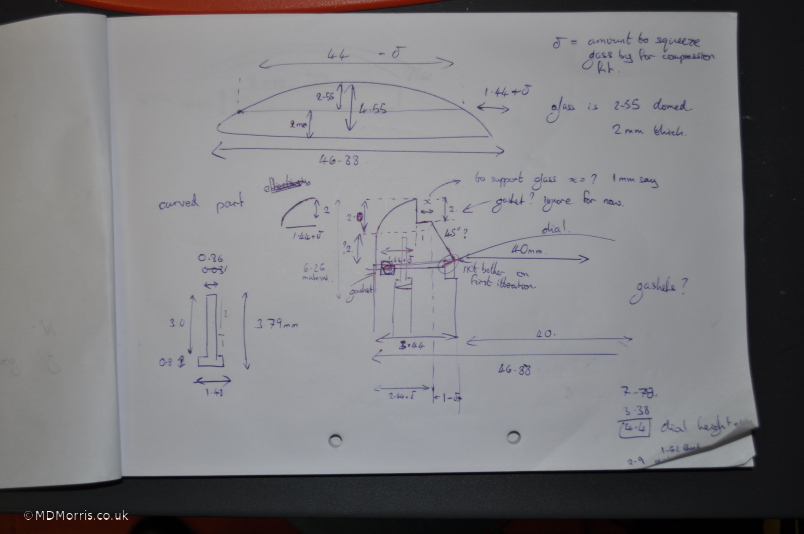
I made some simple plans, above, with the key dimensions. I know it's a bit rough and ready but I didn't see much point in carefully drawing out plans, at this stage, when the real planning is going on as I make the watch itself. The next iteration may be a bit neater!
I'm going to use some screws to hold together the top and middle sections, the screws need to be placed in the watch case sides leaving enough metal to get a good thread. I want these set of screws to be completely concealed in the final watch.
To make accurate positioning of the screw holes, first, the backlash in the lead-screws of the mill need to be managed. I check the backlash in the left-right axis by moving the mill table one increment (0.1mm) to the left and then one increment to the right, so that the mill table should return to the original position. If the value on the dial indicator shows any difference between the start and end values then this is dealt with by either tightening the anti-backlash screws, or adjusting the cnc controller to compensate, or both (usually!)
 .
.
I do the same thing for the forward-backward axis and also for the rotation table. However, with the latter, I will always be progressing the angle in the same direction, so backlash shouldn't be an issue.
 .
.
The next thing to do is centre the rotation table about the milling head
 .
.
I use an edge-finder for this and use it to find the centre like this:
- find the y-axis extreme position of the rotation axis and note it's y-axis value,
- find the opposition y-axis extreme position and note this value too,
- move the y-axis to the mid-point of these extreme positions and zero the y-axis here,
- Now do the same for the x-axis,
- Do the y-axis again, as there may have been a small error in the initial finding of the extreme positions.
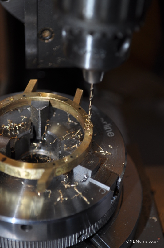
Now I drill some centre holes in four locations
 ,
,
I took this photo to remind me what size drill bit I used. First it was a 1.5mm drill bit,
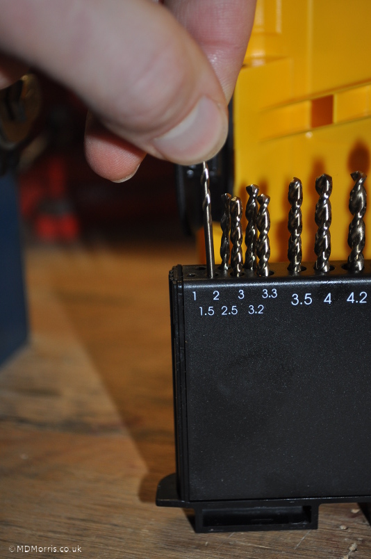
to drill the holes that go all the way through the metal. Then I drilled
 ,
,
with a 2.5mm to a lesser depth. I can't remember the depth at the moment, I'll see if I can find some more notes, but it is to allow the screw to recess into the middle section but not, obviously, so the screw falls right through the hole and out the other side!
Initially I was designing with longer screws in mind and I placed one in the hole I'd cut to check the fit
 ,
,
you can just see the screw in the near left-hand hole.
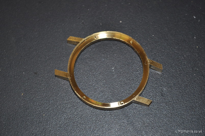
This is how the middle section looks now, from above
 .
.
I did the same thing for the bottom section, cutting smaller diameter holes for putting in the screw thread. Then I tapped the screw thread into the top section holes:
 .
.
I'm using the middle section to help guide the tapping die into a vertical orientation.
Now all the screw threads are cut, time to test the fixing
 ,
,
Yep that's good!
I would like the top section to drop into the middle section to give me more chance at designing some sort of gasket mechanism. The watch will need to have a certain degree of water and dust resistance. So I set about cutting a recess into the middle watch section
 .
.
Here's a close up of the tool position:
 .
.
Bit of cutting .....
bit more cutting .....,
OK the recess is cut, viola!
 ,
,
now I need to do the male-fit equivalent with the top watch section. The next photo is showing me cutting the outer edge off the ring:
 .
.
Here's another showing the progress:
 .
.
The fit is quite tight, so I remove the tooling marks and polish with some wet'n'dry paper.
 .
.
In my design, the top section has some space to accommodate the dial, this is to fix the dial into place when the watch is screwed together. I change the positioning of the clamps and cut out this space now
 .
.
This time I remove the tooling marks and polish with Water of Ary stone substitute as it's very hard to get hold of the proper thing
 ,
,
but it still gives a nice finish.
I make some little adjustments to the dial as it's not quite round enough. For this I linish it on wet and dry paper, with some water
 .
.
Before I take the top section off the lathe it's worth checking that I've cut out enough material,
 ,
,
it's a good fit and I've got to remove the dial with some blue tack stuck to the top as it's too difficult to get it out otherwise.
Ah, OK, in this photo it shows that the top and middle section fit wasn't quite there - it was a bit too tight. Since the ring has been moved out of the chuck I can't cut any more off as it's position won't be exactly the same as before and the resulting cut will be eccentric. So, instead, I file the edge whilst the ring is spinning and take off a little bit more material this way.
 .
.
Now the top and middle sections fit together nicely and there is just the right amount of room for the dial to sit snugly in-between the two
 .
.
From the top of the watch it looks like this:
 ,
,
and here's a different angle
 .
.
The next thing to do is cut the space for the watch glass.